Connectors for Robotics and Industrial Applications Table of Contents:
- WHAT IS THE CONNECTOR'S FUNCTION IN AN ELECTRONIC SYSTEM?
- CONNECTOR TECHNOLOGY
- WHAT ARE THE DIFFERENT CONNECTOR CONTACT TYPES
- WHAT IS THE CONTACT TERMINATION TYPE AND WHY DOES IT MATTER?
- HOW TO FIND THE RIGHT CONNECTOR KEY REQUIREMENTS & SPECIFICATIONS
- WHAT IS THE OPERATING TEMPERATURE RANGE FOR DIFFERENT CONNECTOR TYPES?
- WHAT DETERMINES THE NUMBER OF CONTACTS?
- WHAT IS INSERTION FORCE AND WHY DOES IT MATTER?
- WHAT IS CONTACT (PIN) PITCH?
- WHAT IS INGRESS PROTECTION (IP) RATING
- HOW TO CHOOSE CONNECTORS FOR THE INDUSTRIAL AND ROBOTICS ENVIRONMENT
- RECOMMENDED CONNECTORS FOR ROBOTICS AND INDUSTRIAL APPLICATIONS
- RESOURCES
What is the connector's function in an electronic system?

Connectors play a key role routing signals and power between almost all electronic systems from smartphones to spacecraft. Industrial applications include industrial machines, robotics, aircraft, and many others.
In an industrial application, connectors inside a piece of equipment provide the interface between printed circuit boards (PCBs) and other internal units, allowing them to be manufactured and tested separately before they are combined in the final product. This approach saves cost and time in manufacturing.
At the module level, connectors act as the interface between equipment and the outside world. They also protect sensitive internal electronics from the harsh industrial environment. In this case, the connector not only provides a reliable transfer of signals and power; it also must maintain the integrity of the case design to protect against the intrusion of liquids and dust.
CONNECTORS FOR INDUSTRIAL AND ROBOTICS APPLICATIONS
As automation increases and applications add internet connectivity, there is more pressure than ever before to develop reliable and robust interconnected production and motion control systems.
The Industrial Internet of Things (IIoT) is adding sensors, local processing power, and networking to many traditional industrial machines. These new features are driving the need for reduced size, weight, power consumption, and increased throughput. Space limitations in many applications are calling for connectors that can handle both power and data simultaneously.
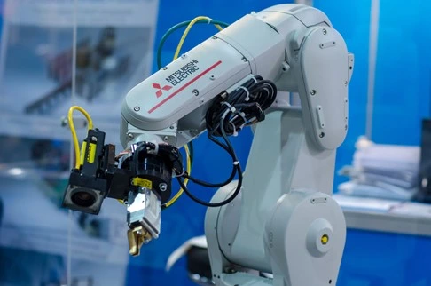
Connectors in industrial robots
Industrial robots (figure 2) are highly complex electro-mechanical machines. They often contain multiple computers, dozens of sensors, hydraulic pumps, multiple motors, and network connections. Connectors in industrial robotics applications are exposed to many of the same conditions as other industrial machines, with the added requirement of continuous motion over the operating life.
The IIoT trend towards adding electronic functions to industrial machines applies to industrial robots, too. End-of-arm (EOA) instruments move sophisticated electronics such as vision systems, with their cameras, microcontrollers (MCUs), and sensors, out to the end of the robot arm. EOA installations allow robots to perform delicate operations such as fault detection or pick-and-place, but they require extremely small, lightweight connectors that can withstand robotic motion and still survive the industrial environment.
As robotic work cells are becoming capable of multiple operations, robotic connectors must be easy to disconnect to swap out different tools or perform maintenance. In addition to the connectors that route signals and power around the industrial machine or robot itself, the human-machine interface (HMI), whether it be wand, tablet, touchscreen or similar, also requires ruggedized industrial connectors for standard interface protocols such as USB, Ethernet, etc.
Industrial robots have expanded beyond traditional settings such as welding on an automotive assembly line. Autonomous delivery robots are becoming standard features in highly-automated factories and are even starting to appear on residential streets; these robots place a premium on small, robust connectors that can handle both data and power.
Connectors for general industrial applications
Industrial connector products include both standard and custom solutions that are engineered with highly reliable contact technologies that maximize operating efficiency and manufacturing uptime.
Several key design features provide an industrial connector with protection from environmental stresses.
- Locking/coupling mechanisms. A robust coupling mechanism is a must for industrial connectors to maintain connectivity in all conditions.
- Housing and insulation. For applications where the connector is likely to be exposed to extremes of temperature, moisture, and dust, a corrosion-resistant metal housing may be the most appropriate option. IP-rated connectors are preferred in many cases. For other industrial uses that require lightweight and flexible connectors, high-temperature resistant plastic composites may be more attractive.
- The shape of the connector, thread pattern or mating mechanism and positioning of pins also play an important role in the creation of a rugged and reliable connector. Circular connectors allow for easier connection and disconnection. They are also easier to seal and less likely to wear or break.
- Many industrial machines operate in the presence of devices such as welders, electric furnaces, and high-power motors that generate high levels of electromatic radiation. Connectors with 360° EMI shielding are preferred in such cases; examples include metal-shell push-pull connectors or D-sub connectors with metallized backshells. Both types are discussed below.
Rugged Environment Certified (REC) is an external testing certification that reinforces the quality and performance of ruggedized harsh-environment connector solutions. These products have been proven to withstand the most challenging environments including oil rigs, weather stations, & ruggedized industrial applications.
CONNECTOR TECHNOLOGY
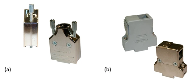
Figure: 3 Construction of a 981 Series right-angle D-sub backshell connector
A typical industrial or robotics connector consists of an outer shell (housing) that protects the internal elements; an internal insulator that holds multiple pins or sockets; a rigid structure that positions the pins securely and prevents them from touching; and a means of securing the connector to the mating receptacle. Figure 3 shows the construction of a D-sub connector with an Armor right-angle backshell suitable for Ethernet connections in space-constrained industrial robotics applications. This connector shell includes a slide latch to lock the connector to the receptacle.
Each element of a connector is available in a choice of materials to suit different applications.
What Are the Different Connector Contact Types?
Connector contacts can be manufactured in several ways. Stamped and formed contacts are designed to provide reliable performance in applications where wire termination costs are of primary concern. Stamped contacts are more suited to high-volume production as they can be fed into automated crimping machines.
Machined contacts offer superior performance than stamped contacts: they offer greater power density, lower contact resistance, and higher current. They also provide better strength and durability; on the other hand they are more expensive.
What Is the Contact Termination Type and Why Does It Matter?
The termination type refers to the method of connecting an individual connector contact to a mating cable or PCB. There are three main types of contact terminations:
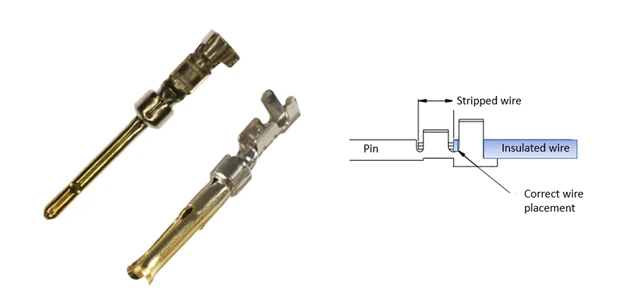
- In a crimp termination (figure 4) , the contact is mechanically tightened (crimped) around the wire to make the electrical contact. Another part of the contact is crimped around the wire insulation to provide strain relief. The contact, with wire attached, is then inserted into the connector housing. A crimping tool is used for the crimping operation.
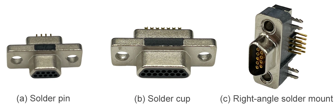
- In a solder termination, each connector pin includes a solder cup or pin on the end to which a wire is soldered. If the connector is to be mounted to a PCB, the pins are inserted through holes in the PCB and then soldered in place. Figure 5 shows the different options.
- Insulation displacement connectors (IDCs) are used to connect insulated wire or cable to a device without pre-stripping the cable or wire. A sharp blade or multiple blades in the connector (figure 6) cuts the insulation and contacts the wire as it is inserted. A ribbon cable is suitable for an IDC termination.
- Connectors with screw terminations allow the wire to be inserted into a receptacle, then secured with a built-in screw as shown in figure 7. These terminations are not as compact as other types, but have the advantage that wire connections can be easily attached or removed in the field.
How to Find the Right Connector - Key Requirements & Specifications
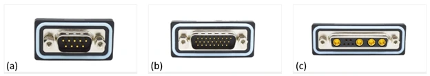
Like any component, a connector comes with a set of key specifications. Many industrial connector types come in standard form factors that are used across multiple applications: the “D” type connector is one example.
Once the connector type has been selected, the designer must also specify a list of key requirements. Here are the main ones:
What is The Operating Temperature Range for Different Connector Types?
Although the operating temperature range of a connector is not critical in a less demanding commercial environment, it is an important consideration when the connector is to be used in an industrial application. The operating temperature range can vary widely depending on the intended application. Here are a few examples; consult the data sheet for specific ratings.
|
Connector type |
Model Family |
Temperature range |
|
circular connector |
-40° to +85°C |
|
|
flanged d-sub IP67 connector |
-25° to +85°C |
|
|
push-pull connector, plastic shell |
-20 ° to + 120 ° C |
|
|
push-pull connector, metal shell |
-40 C to +200 C |
|
|
d-sub IP67 connector |
-55 ° to + 105 °C |
What Determines the Number of Contacts?
When choosing any connector type it is necessary to determine how many pins will be required. This may not only determine the actual connector part, but also the series of connector to be used. Depending on model, connectors may have from 2 up to 240 pin contacts.
Number of mating cycles
All connectors undergo wear each time they are connected and disconnected. Often the life of a connector is specified in terms of the number of mating cycles, i.e., a connection and disconnection. Some connectors intended only to be disconnected for service and repair need a smaller number of mating cycles. Connectors for more general use must have a much larger number. This specification can affect the connector chosen for a particular application.
For sub-d and M-type connectors, the number of mating cycles is up to 750 depending on the type of contacts (machined or stamped and formed) and the gold plating thickness. Push-pull connectors are rated for 5000+ mating cycles. Go here to see the minimum cycle ratings.
What Are The Connector Contact Specifications?
There are several specifications related to the connector contacts, including:
- Maximum wire gage
- Maximum current capability
- Contact resistance
- Maximum working voltage
The number of contacts can influence the contact specifications of a particular connector. A smaller number of contacts allows a larger contact size with greater current capability, lower contact resistance, and higher working voltage. The table below shows the contact specifications of two Quik-Loq™ 820B connectors with different numbers of contacts .
|
Connector P/N |
# of contacts |
Pin diameter (mm/”) |
Max wire size (awg) |
Max current (A) |
Contact resistance (mΩ) |
Working Voltage (V) |
|
820B002 |
2 |
.9/.035 |
22 |
10 |
6 |
330 |
|
820B009 |
9 |
.5/.020 |
28 |
2 |
10 |
200 |
What is Insertion Force and Why Does it Matter?
When male and female contacts connect or disconnect, friction per contact exists between the pair of contacts. The friction provides a good electrical and mechanical connection and cleans the contacts. For a small number of contacts, this friction does not present a problem. D-Sub connectors, for example, have a maximum mating force of 3.3 newtons and a minimum unmating force of 0.25 newtons.
As the number of pins increases, though, so too does the force required to connect and disconnect the two connectors. This can be a problem for high pin-count connectors and may become a design consideration.
For applications that require very large numbers of pins, "Zero Insertion Force" (ZIF) connectors may be used. When mating a ZIF connector, the female connector does not allow the male pins to contact the female mating pins, considerably reducing the force. A lever on the side of the female connector brings them into contact once the two halves have mated. This reduces the insertion force to a very small value.
What Is Contact (Pin) Pitch?
Pitch refers to the distance between adjacent pins. The most common sizes for board level pin and socket pitches are 1.27 mm (0.050”), 2.00 mm, and 2.54 mm (0.1”). Many other pitches are also used: for example Std D-sub uses .109” x .112” and HDD D-Sub uses .090” x .078”.
What Is Ingress Protection (IP) Rating
The IP rating of a connector indicates the level of protection it provides against the incursion of solids, including dust, and liquids, including moisture or water. A connector’s IP rating is expressed in the form “IPXY”, where X and Y are numeric values.
The first digit in an IP rating indicates the level of ingress protection against solid objects ; from IP0x (no protection) to IP6x (complete protection against dust). The second digit refers to protection from liquids: from IPx0 (no protection) to IPx9K (protection against high-pressure steam jets). Ruggedized connectors meet a variety of IP standards: IP50, IP66, IP67, or IP68, depending on the application.
How to Choose Connectors for The Industrial and Robotics Environment
The industrial environment is particularly challenging for connectors. Examples of common industrial applications include:
- Factory Automation Machines
- Material Handling Equipment
- Process Control Systems
- Semiconductor Fabrication
- Machining & Metal Processing
- Food & Beverage Processing
- Pharmaceutical Manufacturing
- Automotive Manufacturing
- Packaging Equipment
- Autonomous Delivery Vehicles
Industrial applications subject connectors to mechanical stresses such as extreme temperature, vibration, shock, or pressure; chemical stresses such as salt water or corrosive chemicals; and a range of electrical stresses.
Let’s look at some of these stresses in more detail.
* Temperature extremes. The majority of environmentally-caused failures are due to excessive temperature or temperature cycling. Most are a result of thermal stress brought on by differences in the coefficients of thermal expansion (CTE) of different materials.
Temperature extremes also affect a connector’s mechanical components. Rubber seals and plastics tend to harden and resist deformation, causing leaks or cracks.
* Shock & Vibration are common in the industrial environment. They can cause mechanical stress in connectors, which results in solder joint cracks, loosening of screws and other fasteners, and metal fatigue. Connectors on industrial equipment are
continuously subject to these mechanical stresses.
* Explosion risk is a concern in oil & gas, coal mining, and wood processing operations. Flammable gases, vapor, dust, or powder are common features of these environments. In such conditions, the making or breaking of a contact – by unplugging a connector, for example - may result in a spark with catastrophic results.
* Rough handling. Many industrial connectors, especially those on portable equipment, are connected and disconnected multiple times in a day, often hurriedly, which increases the risk of wear and tear on the connector. Connectors being dropped or dragged along hard surfaces can damage internal components and can affect the integrity of power or data signals.
* Corrosion caused by exposure to chemicals is an everyday occurrence in industrial environments. The most common combination is high relative humidity coupled with salt fog, which can wreak havoc with electronic components. Common industrial chemicals can also cause corrosion. Examples include both acids – for example sulfuric, chromic, acetic, hydrochloric, or hydrofluoric acid - and bases such as ammonium, potassium, or sodium hydroxides.
Different industrial applications experience a range of environmental hazards, as shown in the following table.
|
Application |
Temperature |
Shock/ Vibration |
Corrosion |
Explosion |
Liquids |
Dust |
|
Industrial |
X |
X |
X |
X |
X |
X |
|
Oil & Gas |
X |
X |
X |
X |
X |
X |
|
Marine/Undersea |
X |
X |
X |
X |
Recommended connectors for robotics and industrial applications
Products recommended for the robotics and industrial markets are discussed in this section. They include Micro-D connectors and cable assemblies: VULCON™ circular connectors; waterproof d-sub connectors; and QUIK-LOQ™ push-pull connectors.
Metric Circular Connectors
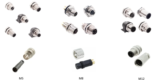
VULCON™ metric circular connectors (Figure above) have screw threads and conform to the DIN EN 61076 standard. These connectors offer a robust waterproof cable-to-panel or cable-to-PC board interface for demanding end-use applications. VULCON™ connectors take up less room than rectangular style connectors with the same pin count, maximizing the use of mounting space. The numerous cabling and pin options have made these circular connectors popular in manufacturing plants in multiple industries due to their flexibility, ruggedness, and reliability. The number after the M indicates size, from small to large.
M12 Circular Connectors
The M12 circular connector has become a leader in the industrial automation and industrial controls sector due to its ability to endure stressful environments and protect against dust while remaining waterproof. M12 industrial applications include automation, remote process sensors, robotics control systems, ruggedized networking, & power conditioning systems. VULCON™ M12 connectors are now available in an upgraded stainless steel version for the most rugged industrial applications. These connectors feature IP67/68 ratings.
M12 connectors come with several types of coding to restrict mating to a defined orientation. In addition, shielding is available in most coded M12 connectors. X-coded M12 connectors, for example, include a cross-shaped shield. Figure 9 shows some common coding configurations.
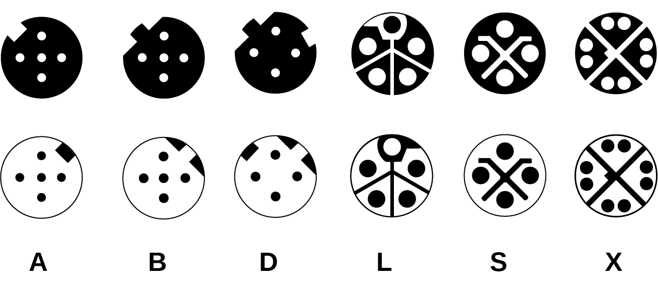
Specified coding schemes are used for defined applications, as shown in the table below:
|
Coding |
Application |
|
A |
Sensors, dc power, 1 Gbit Ethernet |
|
B |
Profibus |
|
D |
100 Mbit Ethernet |
|
L |
PROFINET high power |
|
S |
ac power |
|
X |
10 Gbit Ethernet |
M8 Circular Connectors
The M8 circular connector quickly made its debut as a smaller more compact version of the M12. M8 connectors are used in applications requiring a rugged and robust fully shielded metal shell able to withstand shock and high vibration. M8 industrial applications include ruggedized data loggers & sensors, electronic gauges & metering, avionics, and marine electronics. NorComp offers M8 connectors with A and B coding.
M5 Circular Connectors
M5 connectors are ideal for many applications where a rugged and compact connector solution is required to deliver a secure and reliable signal transfer. M5 connector industrial applications include transportation and control systems, automated doors & ramps, and sensor connectivity.
All metric circular connectors feature IP67/68 protection and are rated over the -40 °C to +85 °C temperature range. The table below shows the options available for each type.
|
Connector |
Contact Count |
Type |
Shield |
|
M5 |
2,3,4 |
cable mount, board mount, panel mount |
Shielded, unshielded |
|
M8 |
3,4,5,6 |
cable mount, board mount, panel mount |
Shielded, unshielded, cable kit |
|
M12 |
3,4,5,6,8,12 |
cable mount, board mount, panel mount, anti-vibration |
Shielded, unshielded, cable kit |
Push-Pull Connectors
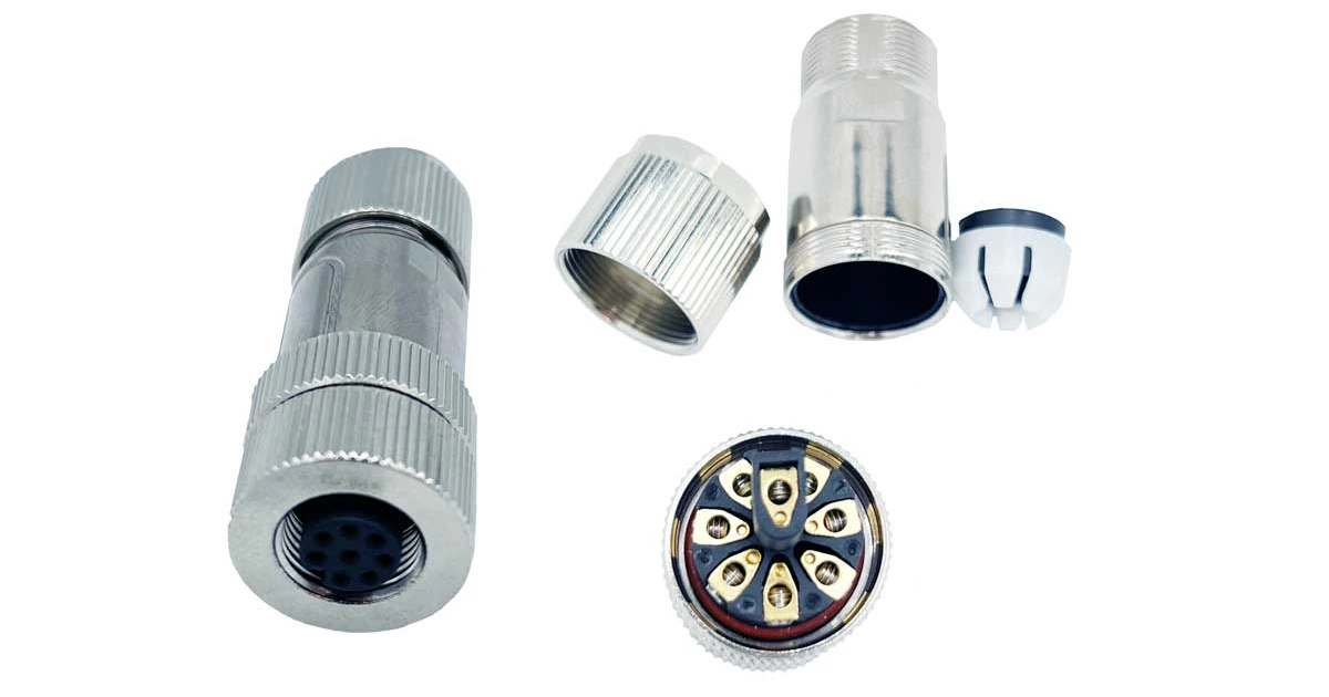
QUIK-LOQ™ Circular Push-Pull Connector systems (figure 10) are rugged, sealed connectors ideal for high-reliability waterproof applications where quick connect / disconnect and environmental protection are required. These connectors provide a convenient solution for industrial systems such as configurable robotic work cells that must switch quickly between multiple modules. Push-pull connectors are rated to REC (Rugged Environment Certified) standards and can withstand high levels of shock and vibration.
There are several families of QUIK-LOQ™ connectors. Features and benefits include:
- Rapid latching release mechanism with alignment key
- Small, rugged precision design
- Available in varying pin positions
- Accepts 14-28 awg wires (based on # of positions)
- Rated for 2 to 30 amps depending on # of positions
- High Mating Cycles (>5000)
- Machined contacts and housing
- 360° shielding for full EMI / RFI
Metal shell push-pull connectors
QUIK-LOQ™ IP50 Push Pull Connector systems are ideal for industrial and robotics markets where high mating cycles & quick connections are called for. The rugged IP50 Push Pull Connectors are engineered with machined contacts and housing for optimal connectivity.
QUIK-LOQ™ IP67 Push Pull Connector Systems are rated for more than 5,000 mating cycles and include alignment keys and rapid latching & release mechanisms. The series features 360° EMI/RFI shielding, and precision-machined contacts for the most reliable signal transfer in heavy-duty environments.
Plastic shell push-pull connectors
The QUIK-LOQ™ line of plastic push pull connectors are recommended for cost-sensitive applications requiring quick connect / disconnect. Industrial markets include medical devices, control systems and test and measurement.
D-Sub connectors
The D-type connector has been used in many applications as a multi-way connector and is well-known as the connector used for RS-232 serial links, although industrial Ethernet or CAN are more common in industrial applications.
Nonetheless, D-subminiature connectors, d-sub backshells, & hoods are still widely used for industrial applications that require a rugged, robust I/O connector system. D-sub connectors are available in solder cup, crimped, and IDC versions depending on model.
There are several families of D-sub connectors. Economical standard D-Sub connectors are available in sizes ranging from 9 pins to 50 pins. These are offered with nickel or tin shells with either crimp or snap-in contacts. High-density D-sub connectors offer greater pin density than the standard versions and are available with 15 to 78 pins.
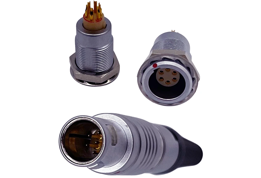
Micro-D connectors
Micro-D connectors are less than one-third the size of standard d-subs and are designed for space-constrained applications that still need a rugged I/O connector system. Examples include EOA systems in industrial robots, and hand-held & portable equipment.
There is a full range of micro-d connectors in 9-pin, 15-pin, and 25-pin configurations with both cable & board mount options. Features include a metal-to-metal interface for robust mechanical connections and effective shielding, machined contacts with a rating of 2 amps, and operation over a temperature range of -40°C to +125°C.
IP-rated D-Sub connectors
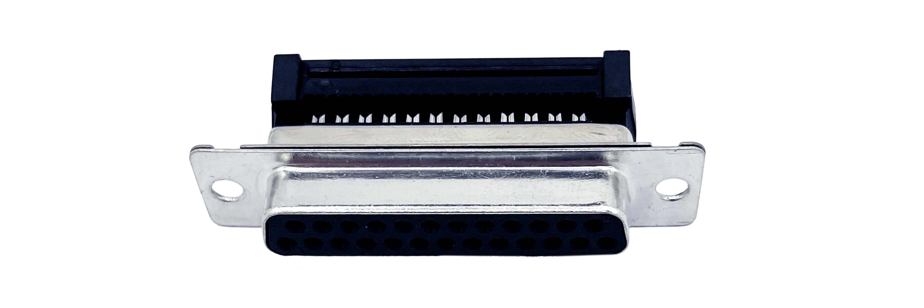
SEAL-D® connectors are designed for applications that require protection from heavy spray or are exposed to short-term submersion. The IP67 rated waterproof d-sub connectors (figure 11) are sealed internally and maintain the same footprint as the standard d-sub product offering. This IP sealing technology allows any existing d-sub product to be manufactured in an IP67-rated version.
SEAL-D® connectors are available in vertical and right-angle board mount types as well as solder cup for panel mount cable applications. Standard D-Subs are available in 9 pin, 15 pin, and 25 pin positions, and high density D-Subs are available in 15-pin, 26-pin, and 44-pin positions. Examples of industrial and robotics applications include:
- Handheld computers, scanners, and printers designed for outdoor use
- Remote sensors, gauges, and data loggers that are exposed to the elements
- Industrial equipment that is routinely subject to wash down
The SEAL-D® family are drop-in replacements for standard unsealed connectors; this eliminates the need to change PCB and sheet metal designs when upgrading to IP67 standards.
NANOOK
flanged waterproof d-sub connectors provide robust IP67-rated performance in standard, high-density, and mixed layout configurations, NANOOK connectors are reliable, cost effective, and operate over a -25°C to +85°C temperature range.
D-Sub backshells
D-sub backshells (figure 13) are designed to maximize EMI/RFI shielding for optimal protection and performance. The comprehensive product offering features a variety of options that improve the connection stability while maximizing cable strain relief to prevent damage to wires and contacts.
ARMOR D-Sub hoods are designed for rugged / robust applications including military, industrial, and aerospace. Featuring an all-metal hood diecast housing, these hoods offer high reliability performance for the most challenging design applications. A wide range of d-sub hood systems is available, including Die-Cast, Metalized Plastic & Plastic versions. A backshell selection guide details the various options.
Power D and Combo-D sub connectors
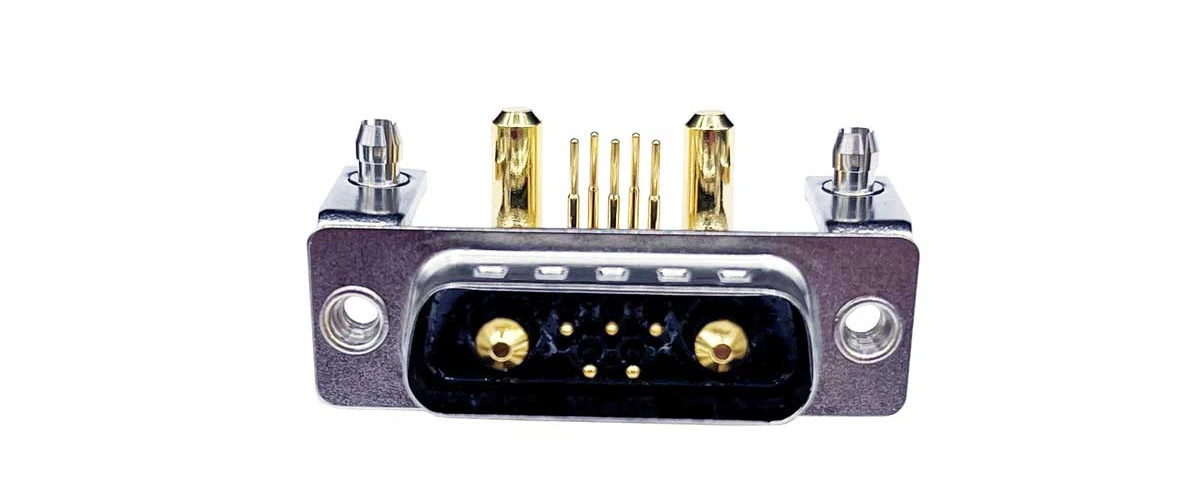
POWER-D & Combo-D mixed contact d-sub connectors are designed for industrial and robotics applications where both power & signal are required from a single connection. Power-D connectors can carry both signal (5 amp) and power (20 / 40 amp) contacts within the same connector body. Featuring “Solid-Pin” machined contacts, these connectors offer high reliability performance for the most challenging design applications.
The product range is ideal for a multitude of both IP-rated and non-rated industrial applications. This diverse combo d-sub product offering includes up to 13 contact configurations engineered for both power & coaxial connector environments such as satellite & weather stations, GPS receivers, transceivers, and radio technology applications. Custom or semi-custom Combo-D connector solutions are also available; these are suitable for applications with modules with unique combinations of signal and power pins, such as robotic work cells.
Coaxial D-sub connectors
Coaxial D-Sub connectors are suitable for industrial audio, video, and RF applications. Available in 5 standard shell sizes with 11 multiple contact arrangements, these reliable, robust connectors provide a combination of signal and coaxial contacts for cable mount, vertical board mount & right-angle board mount terminations.
Custom connectors
Although there are numerous types of standard connectors, they do not satisfy every industrial or robotics application. In such cases, a custom connector and cable solution is often the answer. Examples of one-of-a-kind NorComp designs include:
- Custom connector system for testing a handheld engine and diagnostic system for home construction machinery
- Custom cable assemblies for intelligent battery analyzers and charging systems for the wireless, mobile computing, medical, and transportation industries
- Modification of the standard production flow for D-sub connectors resulting in a unique solution for an industrial customer.
See more custom solutions here. Contact NorComp for more information.
Resources
The NorComp website has several resources for those wishing to learn more about the various types of connectors recommended for industrial and robotics applications. Resources include:
Environmental Compliance statements
White Papers: Custom project success stories
Click on the links or contact us for more information.